Flexible Radar Channel Model for Multi-Dimensional Radar
Published in ICMS, Edinburgh, 2023
Recommended citation: T. G. Pelham
Outline
The development of the networked battlespace as a concept, and the wealth of wired and wireless communications to support it have opened the door to truly multidimensional radar systems. Whether as a static network of radars coordinating to provide national coverage, or a local network for UAV’s providing a swarm aperturefor rapidly reconfigurable airborne radar, there is an urgent need for a flexible radar channel model to empower the engineer and scientist to develop new systems, sensing algorithms and concepts of operation. LyceanEM, an open source electromagnetics model is presented as a solution to this issue, allowing for multi source, heterogeneous antenna arrays to be simulated together with a radar target, and the effects of timing jitter to be explored within the demonstrator system.
In order to model a multi-dimensional radar problem of interest, a cooperative network of three UAVs was chosen, with the example packaged within LyceanEM selected as the host platform. These UAVs are shown in Figure 1, with the lead UAV designated as the origin, and the followers arranged with a spacing of 10m, offset at 45 degrees either side of their common heading which is designated as the positive x direction with a flight altitude of 2km. The second UAV is arranged 10 degrees in elevation above the leader, while the third UAV is arranged 15 degrees `above’. The rendering of the simulation environment for LyceanEM is provided by Open3D. The example UAV design has a total wingspan of 80cm, and an overall length o 50cm. This is meant to represent a small low cost UAV, suitable for short duration missions with a minimal payload.

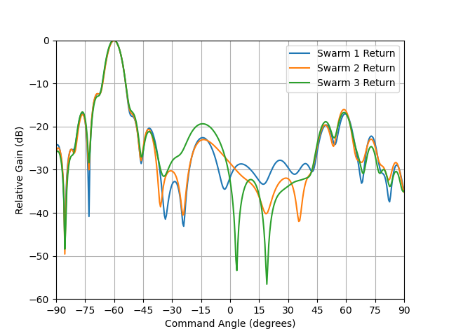
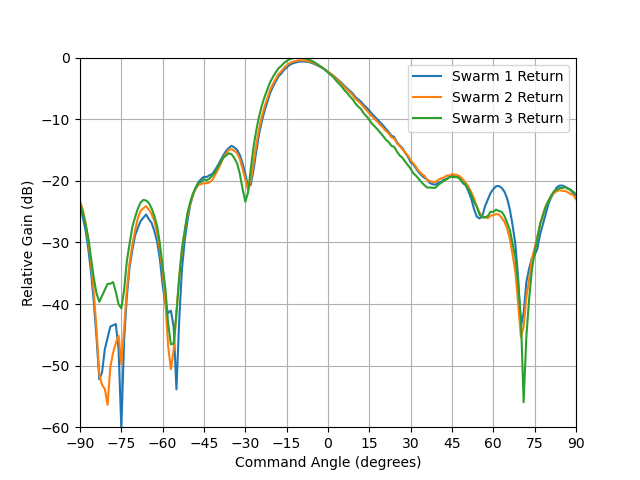
The target of interest in this scenario is another identical UAV, situated 2km away from lead UAV, on a bearing of -60 degrees in azimuth, and -10 degrees in elevation, with a heading of 120 degrees in azimuth. This arrangement places the target at a relative range of 2000m from the lead UAV (designated Swarm 1), 2009.64m from the second UAV (designated Swarm 2), and 1997.81m from the third UAV (designated Swarm 3). The relative bearings of the target from the UAVs are between -10.009 degrees, and -10 degrees in elevation, and -59.7 degrees and -60 degrees in azimuth.

A linear frequency chirp was chosen with a bandwidth of 3GHz, sweeping from 8.5GHz to 11.5GHz over a pulse time of 20ns. The pulse power was chosen as 1W, suitable for the small UAV used in the example, and transmitted by the lead UAS (Swarm 1).


